This is Photoshop’s version of Lorem Ipsn gravida nibh vel velit auctor aliquet.Aenean sollicitudin, lorem quis bibendum auci. Proin gravida nibh vel veliau ctor aliquenean.

FOLLOW ME ON INSTAGRAM

+01145928421
mymail@gmail.com

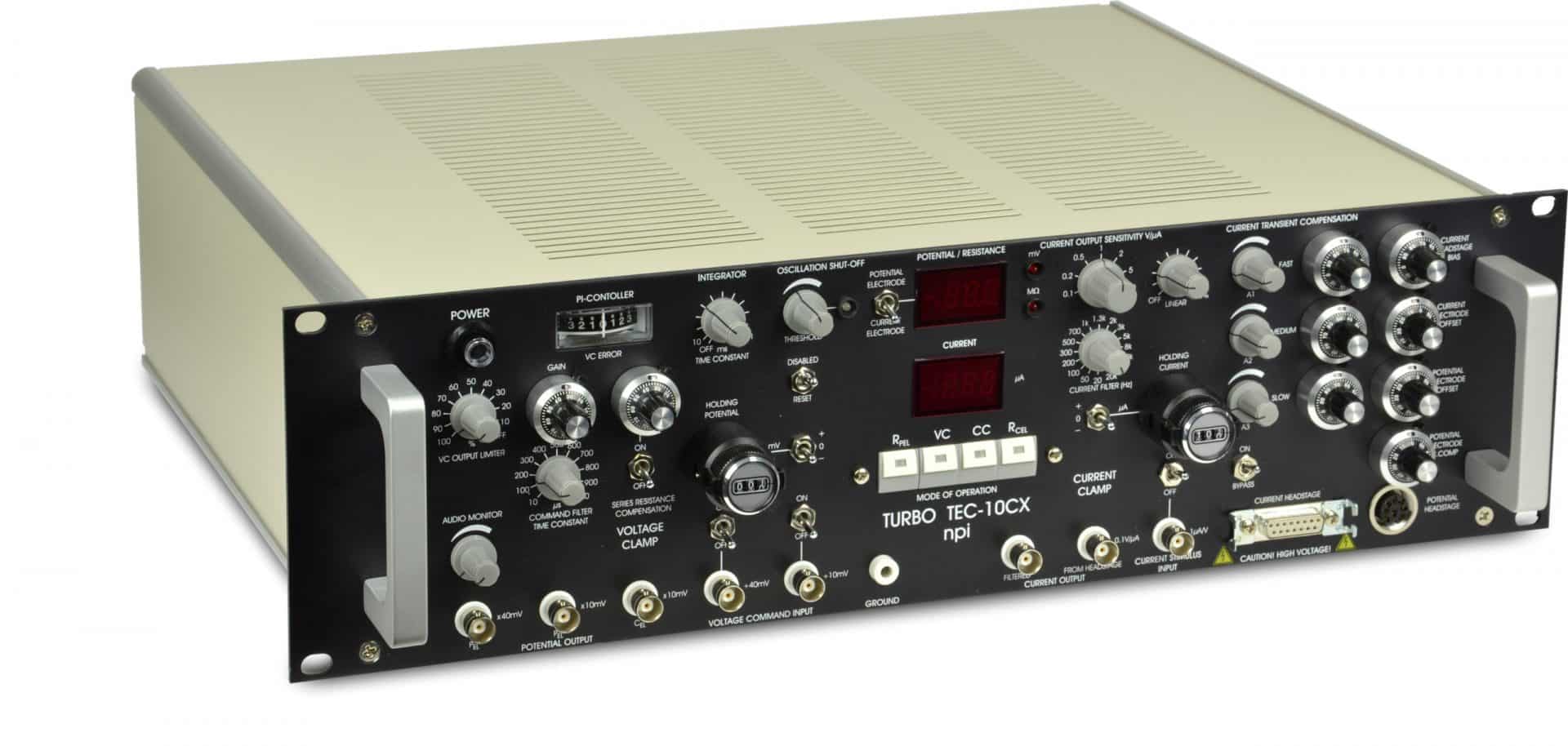
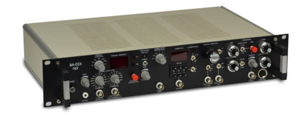
TEC-10CX – Two Electrode Clamp for Oocytes

Add to Wishlist Remove from Wishlist

Two-Electrode Voltage Clamp Amplifier for sophisticated recordings from oocytes

  • Fastest oocyte clamp system on the market
  • Easy setup – no “virtual ground” electrode necessary
  • Superior performance due to npi’s PI control
  • A simpler version is available: TEC-03X

Features

Feature TEC-03X TEC-05X TEC-10CX
VC-Error display X X
PI-Controller X X X
Series Resistance Compensation X X X
Electrode Resistance Test X X X
Mode of Operation Switch Rotary switch Rotary switch Push buttons
Bridge Mode X
Lowpass filter: 20 … 20 kHz Four-Pole BESSEL Four-Pole BESSEL Four-Pole BESSEL
Direct Current output from Headstage X X X
Oscillation Shut-off X X X
Transient Compensation X
Capacity Compensation X X X
Cap. Comp. of Current Headstage X

Please note: These are the available standard configurations. If you have special requirements, please contact us directly.


Ordering

Part no. Description
TEC-10CX TEC-10CX Oocyte Clamp with Digital Filter, Gain & Transient Compensation
TEC-10X TEC-10CX Oocyte Clamp without Transient Compensation, with Digital Filter, Gain
TEC-EH PPH-0P-BNC Microelectrode Holder 1.5 mm glass, w/o. port, w. BNC connector
TEC-EH-SET Electrode Holder Set for TEC Amplifiers
TEC-MOD Passive Cell Model for TEC Systems
TEC-CON SubClic Cable for TEC Headstage
TEC-CHS-4 Current Headstage with four Ranges x0.1,x1,x2,x5
TEC-CHS-4S Current Headstage with four Ranges x0.1,x0.2, x0.5, x1
TEC-RS-R Additional system for measuring series resistance in Oocytes


Technical Data

MODES OF OPERATION


CC:                        Current Clamp mode

VC:                        Voltage Clamp mode

OFF:                      Current- and Voltage Clamp disabled

EXTERN:              External control mode; the mode of operation can be set by a TTL pulse applied to the MODE SELECT BNC. If CellWorks is used, some functions can be controlled from CellWorks (TEC-10CX-CW)

MODE selection:   toggle switch, LED indicators; remote selection by TTL pulse


HEADSTAGES
Potential headstage:


Differential input (for suppression of bath potentials), cmr > 80 dB; Input resistance: >1013 W; operating voltage ±15 V

Electrode connector:              BNC with driven shield; driven shield range: ±15 V, output impedance 250 W

Reference connector (bath):   gold-plated SUBCLIC, grounded shield

Ground connector:                 2.3 mm connector or headstage enclosure

Size:                                        65x25x25 mm, headstage enclosure is connected to ground

Holding bar:                           diameter 8 mm, length 10 cm


Current headstage:


Operating voltage range: ±150 V

Input resistance:              >1012 W (can be internally trimmed)

Electrode connector:       gold-plated SUBVIS connector, grounded shield

Power dissipation:           6 W

Size:                                 100x60x40 mm, grounded enclosure

Holding bar:                    diameter 8mm, length 10 cm


Current range: 150 µA / 1 MW (standard)

Current range switch (optional):        x0.1, x1, x2, x5 (other ranges available)


Bandwidth and speed of response: Full power bandwidth (REL = 0):     >100 kHz

Rise time (10-90%):                         <30 µs (current pulse of 100 µA applied to REL = 1 MW)

Bandwidth switch:                          wide band or 10 Hz for simultaneous patch clamp recordings


Current electrode parameter controls: Leakage current:                              adjustable to zero with ten-turn control

Offset compensation:                      ten-turn control, ±1200 mV


Potential electrode parameter controls: Capacity compensation:                   range 0-30 pF, ten turn control

Offset compensation:                      ±200 mV, ten-turn control


POTENTIAL OUTPUTS


Potential electrode:                two outputs, sensitivity x10 mV and x40 mV, output impedance 250 W; output voltage range ±15 V

Current electrode:                  sensitivity x10 mV; output impedance 250 W,
output voltage range ±15 V

DISPLAY (switch selected): XXX mV


AUDIO MONITOR: Pitch correlated with potential signals


OSCILLATION SHUT-OFF: Turns off current injection and capacity compensation, function indicated by red / green LED, disabled / off / reset switch, threshold set with linear control (0-1200 mV)


ELECTRODE RESISTANCE TEST (both electrodes): 100 mV / MW, obtained by application of square current pulses ±10 nA, display XX.X MW, selected automatically


CURRENT OUTPUTS: Uncompensated output signal:   sensitivity 0.1 V/µA, output impedance 250 W, output voltage range ±15 V

Compensated /filtered output:    sensitivity: 0.1…10 V / µA (0.1, 0.2, 0.5, 1, 2, 5, 10 V / µA) steps selected by rotary switch, with low-pass Bessel filter, output impedance 250 W

Sensitivity monitor:                     +1…+7 Volt, 1V / switch position, output impedance 250 W

DISPLAY:                                  X.XX µA


CURRENT OUTPUT FILTERS: Four-pole low-pass Bessel filter

16 corner frequencies:     20, 50, 100, 200, 300 500, 700, 1k, 1.3k, 2k, 3k, 5k, 8k, 10k, 13k, 20k Hz.

Frequency monitor:         -8…+7 V, 1 Volt / switch position, output impedance 250 W


CURRENT CLAMP Inputs:                        1 µA /V

Input resistance:         >100 kW

HOLD:                       X.XX µA, ten-turn digital control with -/0/+ switch, maximum 10 µA.


Noise (in current clamp): Potential output:         100 µV pp

Current output:           200 pA pp with 1 MW resistance and 10 kHz bandwidth (internal four-pole Bessel filters)


Speed of response (in current clamp):


(1% settling time; potential output signals after application of square pulses of 1V with 1 MW electrode resistance)

Potential electrode:    <10 µs

Current electrode:      <50 µs


VOLTAGE CLAMP: Input sensitivity:                                   :10 mV

Input resistance                                    >100 kW

HOLD:                                                 XXX mV, ten-turn digital control with +/0/- switch, maximum 1000 mV

RISE TIME LIMIT:                             0-0.2 ms

GAIN:                                                  10 µA/V – 10000 µA/V ,ten-turn linear control.

INTEGRATOR TIME CONSTANT: 200 µs – 2 ms, ten-turn control.

OUTPUT CURRENT LIMIT:             0-100% linear control.


Noise (in voltage clamp):


filters set to 10 kHz, other settings see below

Potential output:                                   <100 µV pp

Current output:                                     <10 nA pp at 10 kHz, < 2 nA at 500 Hz


Speed of response (in voltage clamp): 1 % settling time:   < 80 µs for 10 mV step and < 100 µs for 100 mV step applied to cell model (Re = 1 MW, Rm = 100 kW, Cm = 0.1 µF)
POWER REQUIREMENTS: 115/230 V AC, 60 W (0.630 / 0.315 A fuse)


DIMENSIONS: 19″ rackmount cabinet, 19″ (483 mm) wide, 14″ (355 mm) deep, 5.25″(132.5 mm) high


WEIGHT:


8 kg


Downloads

Manuals TEC10CX_manual
Brochure TEC Series

ABOUT

TEC-10CX Two-Electrode Voltage Clamp Amplifier for sophisticated recordings from oocytes

Features:

  • Sophisticated and extremely fast two-electrode voltage and current clamp (V/C) amplifier with PI-controller for recordings from oocytes
  • Push buttons for comfortable and fast selection of MODE of OPERATION
  • Differential potential registration and high-voltage current source output, automated electrode resistance test mode which can be used even with the electrodes impaled in an oocyte
  • VC OUTPUT LIMITER, COMMAND FILTER, INTEGRATOR and SERIES RESISTANCE COMPENSATION for fine tuning of VC circuit
  • Current transient compensation prevents data acquisition system from clipping
  • Digital DISPLAYS for current, voltage and electrode resistance
  • Four-pole BESSEL filter for current
  • No virtual ground needed for recording membrane currents
  • OSCILLATION SHUT-OFF unit prevents cells from damage
  • Standard current range is ±150 µA into 1 MOhm. Current headstages with selectable current ranges (x0.1, x1, x2, x5 or x0.1, x0.2, x0.5, x1) are also available
  • Easy operation with all major data acquisition systems, remote selection of MODE of OPERATION, telegraphing (monitoring) outputs for current sensitivity and filter

Features

Features

Feature TEC-03X TEC-05X TEC-10CX
VC-Error display X X
PI-Controller X X X
Series Resistance Compensation X X X
Electrode Resistance Test X X X
Mode of Operation Switch Rotary switch Rotary switch Push buttons
Bridge Mode X
Lowpass filter: 20 … 20 kHz Four-Pole BESSEL Four-Pole BESSEL Four-Pole BESSEL
Direct Current output from Headstage X X X
Oscillation Shut-off X X X
Transient Compensation X
Capacity Compensation X X X
Cap. Comp. of Current Headstage X

Please note: These are the available standard configurations. If you have special requirements, please contact us directly.


Ordering

Ordering

Part no. Description
TEC-10CX TEC-10CX Oocyte Clamp with Digital Filter, Gain & Transient Compensation
TEC-10X TEC-10CX Oocyte Clamp without Transient Compensation, with Digital Filter, Gain
TEC-EH PPH-0P-BNC Microelectrode Holder 1.5 mm glass, w/o. port, w. BNC connector
TEC-EH-SET Electrode Holder Set for TEC Amplifiers
TEC-MOD Passive Cell Model for TEC Systems
TEC-CON SubClic Cable for TEC Headstage
TEC-CHS-4 Current Headstage with four Ranges x0.1,x1,x2,x5
TEC-CHS-4S Current Headstage with four Ranges x0.1,x0.2, x0.5, x1
TEC-RS-R Additional system for measuring series resistance in Oocytes


Technical Data

Technical Data

MODES OF OPERATION


CC:                        Current Clamp mode

VC:                        Voltage Clamp mode

OFF:                      Current- and Voltage Clamp disabled

EXTERN:              External control mode; the mode of operation can be set by a TTL pulse applied to the MODE SELECT BNC. If CellWorks is used, some functions can be controlled from CellWorks (TEC-10CX-CW)

MODE selection:   toggle switch, LED indicators; remote selection by TTL pulse


HEADSTAGES
Potential headstage:


Differential input (for suppression of bath potentials), cmr > 80 dB; Input resistance: >1013 W; operating voltage ±15 V

Electrode connector:              BNC with driven shield; driven shield range: ±15 V, output impedance 250 W

Reference connector (bath):   gold-plated SUBCLIC, grounded shield

Ground connector:                 2.3 mm connector or headstage enclosure

Size:                                        65x25x25 mm, headstage enclosure is connected to ground

Holding bar:                           diameter 8 mm, length 10 cm


Current headstage:


Operating voltage range: ±150 V

Input resistance:              >1012 W (can be internally trimmed)

Electrode connector:       gold-plated SUBVIS connector, grounded shield

Power dissipation:           6 W

Size:                                 100x60x40 mm, grounded enclosure

Holding bar:                    diameter 8mm, length 10 cm


Current range: 150 µA / 1 MW (standard)

Current range switch (optional):        x0.1, x1, x2, x5 (other ranges available)


Bandwidth and speed of response: Full power bandwidth (REL = 0):     >100 kHz

Rise time (10-90%):                         <30 µs (current pulse of 100 µA applied to REL = 1 MW)

Bandwidth switch:                          wide band or 10 Hz for simultaneous patch clamp recordings


Current electrode parameter controls: Leakage current:                              adjustable to zero with ten-turn control

Offset compensation:                      ten-turn control, ±1200 mV


Potential electrode parameter controls: Capacity compensation:                   range 0-30 pF, ten turn control

Offset compensation:                      ±200 mV, ten-turn control


POTENTIAL OUTPUTS


Potential electrode:                two outputs, sensitivity x10 mV and x40 mV, output impedance 250 W; output voltage range ±15 V

Current electrode:                  sensitivity x10 mV; output impedance 250 W,
output voltage range ±15 V

DISPLAY (switch selected): XXX mV


AUDIO MONITOR: Pitch correlated with potential signals


OSCILLATION SHUT-OFF: Turns off current injection and capacity compensation, function indicated by red / green LED, disabled / off / reset switch, threshold set with linear control (0-1200 mV)


ELECTRODE RESISTANCE TEST (both electrodes): 100 mV / MW, obtained by application of square current pulses ±10 nA, display XX.X MW, selected automatically


CURRENT OUTPUTS: Uncompensated output signal:   sensitivity 0.1 V/µA, output impedance 250 W, output voltage range ±15 V

Compensated /filtered output:    sensitivity: 0.1…10 V / µA (0.1, 0.2, 0.5, 1, 2, 5, 10 V / µA) steps selected by rotary switch, with low-pass Bessel filter, output impedance 250 W

Sensitivity monitor:                     +1…+7 Volt, 1V / switch position, output impedance 250 W

DISPLAY:                                  X.XX µA


CURRENT OUTPUT FILTERS: Four-pole low-pass Bessel filter

16 corner frequencies:     20, 50, 100, 200, 300 500, 700, 1k, 1.3k, 2k, 3k, 5k, 8k, 10k, 13k, 20k Hz.

Frequency monitor:         -8…+7 V, 1 Volt / switch position, output impedance 250 W


CURRENT CLAMP Inputs:                        1 µA /V

Input resistance:         >100 kW

HOLD:                       X.XX µA, ten-turn digital control with -/0/+ switch, maximum 10 µA.


Noise (in current clamp): Potential output:         100 µV pp

Current output:           200 pA pp with 1 MW resistance and 10 kHz bandwidth (internal four-pole Bessel filters)


Speed of response (in current clamp):


(1% settling time; potential output signals after application of square pulses of 1V with 1 MW electrode resistance)

Potential electrode:    <10 µs

Current electrode:      <50 µs


VOLTAGE CLAMP: Input sensitivity:                                   :10 mV

Input resistance                                    >100 kW

HOLD:                                                 XXX mV, ten-turn digital control with +/0/- switch, maximum 1000 mV

RISE TIME LIMIT:                             0-0.2 ms

GAIN:                                                  10 µA/V – 10000 µA/V ,ten-turn linear control.

INTEGRATOR TIME CONSTANT: 200 µs – 2 ms, ten-turn control.

OUTPUT CURRENT LIMIT:             0-100% linear control.


Noise (in voltage clamp):


filters set to 10 kHz, other settings see below

Potential output:                                   <100 µV pp

Current output:                                     <10 nA pp at 10 kHz, < 2 nA at 500 Hz


Speed of response (in voltage clamp): 1 % settling time:   < 80 µs for 10 mV step and < 100 µs for 100 mV step applied to cell model (Re = 1 MW, Rm = 100 kW, Cm = 0.1 µF)
POWER REQUIREMENTS: 115/230 V AC, 60 W (0.630 / 0.315 A fuse)


DIMENSIONS: 19″ rackmount cabinet, 19″ (483 mm) wide, 14″ (355 mm) deep, 5.25″(132.5 mm) high


WEIGHT:


8 kg


Downloads

Downloads

Manuals TEC10CX_manual
Brochure TEC Series