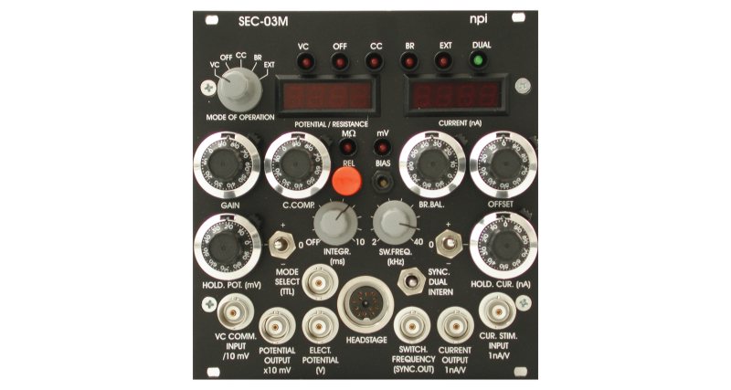
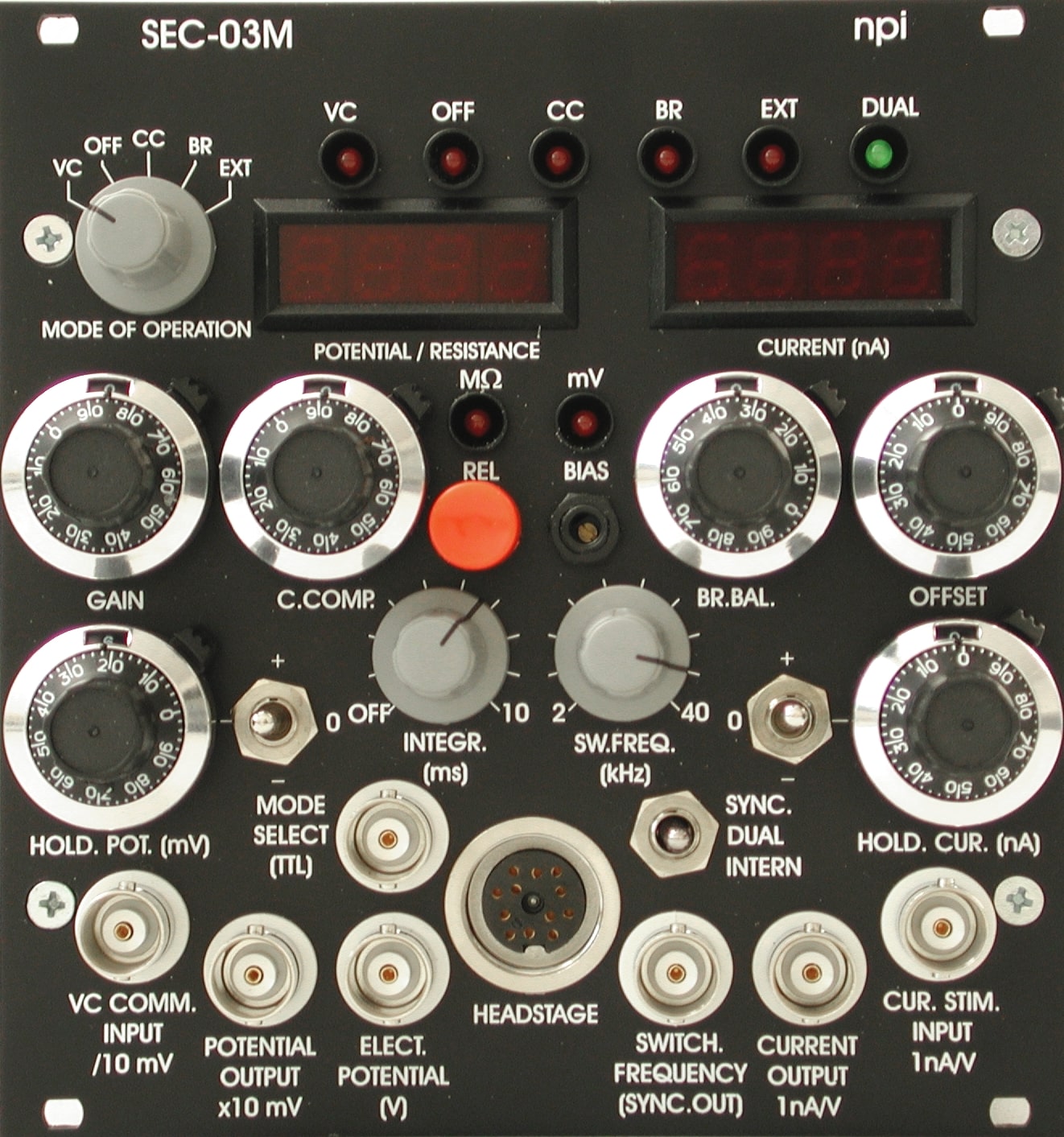
| MODES OF OPERATION |
VC: Voltage Clamp mode (discontinuous)
CC: Current Clamp mode (discontinuous)
OFF: Current- and Voltage Clamp disabled
BR: Bridge Mode (continuous CC)
EXT: External control mode
MODE selection: toggle switch, LED indicators |
| HEADSTAGES |
Standard headstage
Operation voltage: ±15 V
Input resistance: <1013 Ω (internally adjustable)
Current range (continuous mode): 120 nA into 100 MΩ
CC control: Coarse control for input capacity compensation
Electrode connector: gold plated SUBCLIC (SMB) with driven shield
Driven shield output: 2.3 mm connector, range ±15 V, impedance 250 Ω
Ground: 2.3 mm connector or headstage enclosure
Holding bar: diameter 8 mm, length 150 mm
Size: 100x40x25 mm
Headstage enclosure is connected to groundLow noise (whole-cell) headstage (SEC-HSP)
Operation voltage: ±15 V
Input resistance: <1013 Ω (internally adjustable)
Current range (continuous mode): 12 nA into 100 MΩ
external CC control: Coarse control for input capacity compensation
Electrode connector: BNC connector with driven shield
Driven shield output: 1 mm connector, range ±15 V, impedance 250 Ω
Ground: 1 mm connector or headstage enclosure
Mounting plate: 60×50 mm with four 6 mm holes
Headstage enclosure is connected to groundDifferential input headstage (SEC-HSD)
Operation voltage: ±15 V
Input resistance: <1013 Ω (internally adjustable)
CMR: >90 dB
Current range (continuous mode): 120 nA into 100 MΩ
CC control: Coarse control for input capacity compensation
Electrode connectors: two gold plated SUBCLIC (SMB) with driven shields
Driven shield output: 2.3 mm connector, range ±15 V, impedance 250 Ω
Ground: 2.3 mm connector or headstage enclosure
Holding bar: diameter 8 mm, length 100 mm
Size: 100x40x25 mm
Headstage enclosure is connected to ground |
| ELECTRODE PARAMETER CONTROLS |
Offset: ten-turn control, ±200 mV
Capacity compensation: range 0-30 pF
adapts compensation circuit to electrode parameters
coarse control at headstage
fine control at front panel: ten-turn potentiometer |
| BANDWIDTH and SPEED OF RESPONSE |
Full power bandwidth (REL = 0): >100 kHz
Rise time (10-90%, REL = 100 MΩ): <30 µs
Rise time (10-90%, REL = 5 MΩ): <8 µs
Electrode artifact decay
(switched modes, 10 nA signal): <1 µs (REL = 5 MΩ); <1.5 µs (REL = 100 MΩ) CAPACITY COMPENSATION tuned with no overshoot. |
| ELECTRODE RESISTANCE TEST |
obtained by application of square current pulses ±1 nA; 10 mV/MΩ; display XXX MΩ |
| CELL PENETRATION |
Overcompensation of capacity compensation, fixed timed |
| SWITCHED MODES PARAMETERS |
Switching frequency: linear control, 2-40 kHz; duty cycle: fixed to ¼ (25% current injection) |
| CURRENT RANGE in SWITCHED MODE |
Standard headstage: ±30 nA
SEC-HSP headstage: ±3 nA |
| SWITCHED MODE OUTPUTS |
Electrode potential: max. ±12 V, output impedance: 250 Ω
Switching frequency: TTL, output impedance: 250 Ω |
| CURRENT OUTPUT |
10 nA / V; output impedance: 250 Ω; current display: X.XX nA |
| POTENTIAL OUPUT |
Sensitivity: x10 mV; output impedance: 250 Ω; potential display: XXX mV |
| CURRENT CLAMP |
Input: 1 nA/V; input resistance: >100 kΩ
HOLD: X.XX nA, ten-turn digital control with -/0/+ switch, max. 10 nA
BRIDGE balance : XXX MΩ with ten-turn digital control
Noise (BRIDGE MODE): 400 µVpp / pApp with 100 MΩ resistance at 10 kHz bw |
| VOLTAGE CLAMP |
Input: /10 mV; input resistance >100 kΩ
HOLD: XXX mV, ten-turn digital control with +/0/- switch, max. 1000 mV
GAIN: 100 nA/V – 10 µA/V ten-turn linear control
Noise: potential output: <400 µVpp, current output: <400 pApp. |
| SPEED of RESPONSE (VC Mode) |
1 % settling time: <80 µs for 10 mV step and <800 µs for 50 mV step applied to a cell model
(REL = 100 MΩ, Rm = 50 MΩ, Cm = 470 pF, switching frequency = 30 kHz, standard headstage) |
| DIMENSIONS |
24 HP (121.5 mm) x 3U (128.5 mm) x 7 inch (175 mm) deep |
|
|


