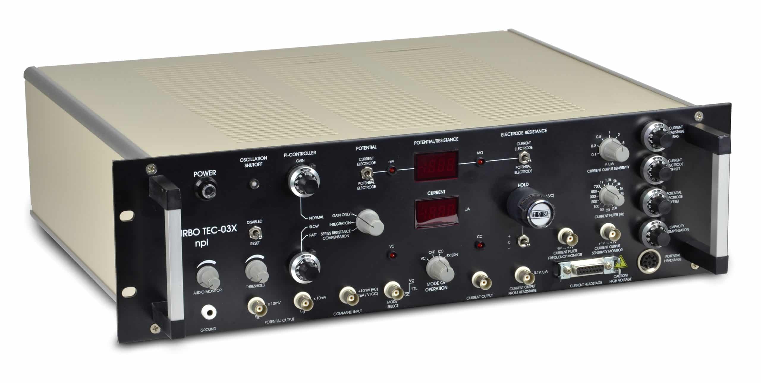
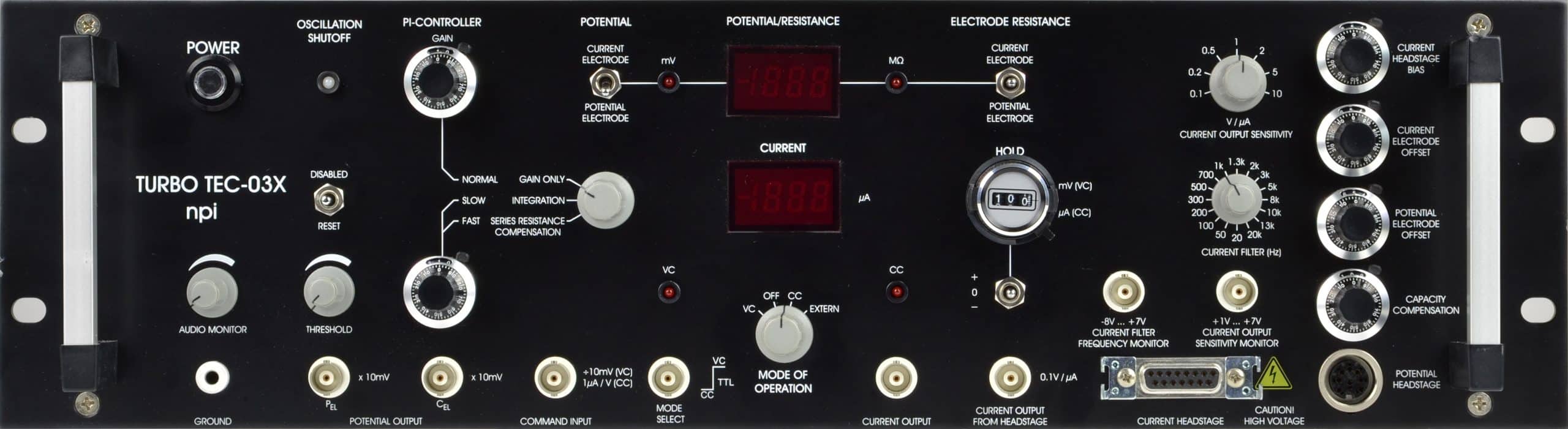
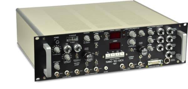
| MODES OF OPERATION |
VC: Voltage Clamp mode |
| OFF: Membrane potential recording only |
| CC: Current Clamp mode |
| EXT (TTL): External control by TTL |
|
MODE selection: toggle switch, LED indicators; remote selection by TTL pulse |
| HEADSTAGES |
|
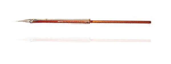
| Potential headstage: |
Differential input (for suppression of bath potentials), cmr > 80 dB; Input resistance: >1013 Ω; operating voltage ±15 V |
| Electrode connector: BNC with driven shield; driven shield range: ±15 V, output impedance 250 Ω |
| Reference connector (bath): gold-plated SMB, grounded shield |
| Ground connector: 2.3 mm connector or headstage enclosure |
| Size: 65x25x25 mm, headstage enclosure is connected to ground |
| Holding bar: diameter 8 mm, length 10 cm |
| Current headstage: |
Operating voltage range: ±150 V |
| Input resistance: >1012 Ω (can be internally trimmed) |
| Electrode connector: gold-plated SMC connector, grounded shield |
| Power dissipation: 6 W |
| Size: 100x60x40 mm, grounded enclosure |
| Current range: |
150 µA into 1 MΩ (standard) |
| Current range switch (optional): x0.1, x1, x2, x5 (other ranges available) |
| Bandwidth and speed of response: |
Full power bandwidth (REL = 0): >100 kHz |
| Rise time (10-90%): <30 µs (current pulse of 100 µA applied to REL = 1 MΩ) |
| Bandwidth switch: wide band or 10 Hz for simultaneous patch clamp recordings |
| Current electrode parameter controls: |
Leakage current: adjustable to zero with ten-turn control |
| Offset compensation: , ±500 mV, ten-turn control |
| Potential electrode parameter controls: |
Capacity compensation: range 0-30 pF, ten turn control |
| Offset compensation: ±300 mV, ten-turn control |
| POTENTIAL OUTPUTS |
Potential electrode: sensitivity x10 mV, output impedance 50 Ω; output voltage range ±15 V |
| Current electrode: sensitivity x10 mV; output impedance 250 Ω, output voltage range ±15 V |
| DISPLAY (switch selected): XXX mV |
| AUDIO MONITOR: |
Pitch correlated with potential signals |
| OSCILLATION SHUT-OFF: |
Turns off current injection and capacity compensation, function indicated by red / green LED, disabled / off / reset switch, threshold set with linear control (0-1200 mV) |
| ELECTRODE RESISTANCE TEST (both electrodes): |
100 mV / MΩ, obtained by application of square current pulses ±10 nA, DISPLAY (switch selected): XX.X MΩ |
| CURRENT OUTPUTS: |
Uncompensated output signal: sensitivity 0.1 V/µA, output impedance 50 Ω, output voltage range ±15 V |
| Compensated /filtered output: sensitivity: 0.1…10 V / µA (0.1, 0.2, 0.5, 1, 2, 5, 10 V / µA) steps selected by rotary switch, with low-pass Bessel filter, output impedance 50 Ω |
| Sensitivity monitor: +1…+7 Volt, 1V / switch position, output impedance 50 Ω |
| DISPLAY: X.XX µA |
| CURRENT OUTPUT FILTERS: |
Four-pole low-pass Bessel filter |
| 16 corner frequencies: 20, 50, 100, 200, 300 500, 700, 1k, 1.3k, 2k, 3k, 5k, 8k, 10k, 13k, 20k Hz. |
| Frequency monitor: -8…+7 V, 1 Volt / switch position, output impedance 50 Ω |
| CURRENT CLAMP |
Inputs: 1 µA /V |
| Input resistance: >100 kΩ |
| HOLD: X.XX µA, ten-turn digital control with -/0/+ switch, maximum 10 µA. |
| Noise (in current clamp): |
Potential output: 100 µV pp |
| Current output: 200 pA pp with 1 MΩ resistance and 10 kHz bandwidth (internal four-pole Bessel filters) |
| VOLTAGE CLAMP: |
Input sensitivity: :10 mV |
| Input resistance >100 kΩ |
| HOLD: XXX mV, ten-turn digital control with +/0/- switch, maximum 1000 mV |
| GAIN: 10 µA/V – 10000 µA/V , ten-turn linear control. |
| INTEGRATOR TIME CONSTANT: 100 µs – 10 ms, potentiometer. |
| Noise (in voltage clamp): |
filters set to 10 kHz, other settings see below |
| Potential output: <100 µV pp |
| Current output: <10 nA pp at 10 kHz, < 2 nA at 500 Hz |
| POWER REQUIREMENTS: |
115/230 V AC, 60 W (1.25 / 0.63 A fuse, slow) |
| DIMENSIONS: |
19″ rackmount cabinet, 19″ (483 mm) wide, 14″ (355 mm) deep, 5.25″(132.5 mm) high |
| WEIGHT: |
8 kg |