About LL-2
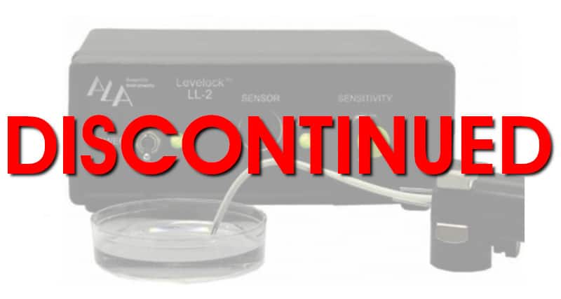
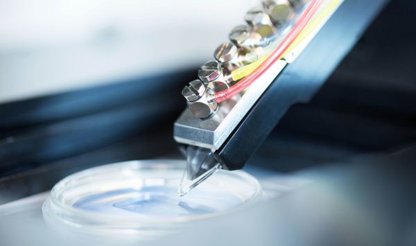
 The LevelLockTM uses a fiber optic cable with a section of the insulator removed. The fiber is bent 180o at the exposed point and as it contacts the surface of a liquid a percentage of the IR light is absorbed, depending on the depth of the sensor.
This analog signal is translated into valve activity in relation to the surface position. When the fluid surface just touches the sensor, or is below the sensor, the valve is inactive. As soon the fluid height crosses a threshold on the sensor, the valve begins to function. As the fluid advances up the sensor, valve activity increases to an eventual maximum. A suction source (such as the VWK) attached to the back of the LevelLockTM controller box pulls the solution to waste as the valve meters it out.
There are three main items in the fluid flow pathway to theLeveLockTM. The first is a check valve, which should be located within inches of the chamber. The second is a shock baffle, that consists of a syringe on a stand. The third is a filter to protect and prolong the life of the valve.
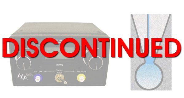
The shock baffle and filter should be kept close to the LeveLockTM.A suction source (such as the VWK) must be connected to the back of the LL-2 and have a collection chamber to gather all the effluent for disposal. The vacuum source need not be greater than -17 KPa – a strong vacuum source should be attenuated with a needle valve to reduce suction.


